AUTOMATIXARON
Introduction to RoboDK
Aim of the lesson:
In this lesson, we will familiarize with the RoboDK software, by setting up a simple environment, testing different robot movements, and operations, and generating the written program.
RoboDK software:
RoboDk is an offline simulator program for any industrial robot, with one simulation environment. It has an online library for different robots (ex.: Kuka, Puma, Universal, etc.), tools (ex.: grippers, welder gun, extruder, etc.), objects (ex.: conveyor belt, table, etc.). We can write robot programs and python scripts as well. We can design custom robotic manipulators if we can't find one online. RoboDK generates the specific robot program script for every robot type.
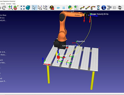
Environment setup:
Open RoboDK, and the online library.
-
Search for KUKA brand, and add the KR 10 R900 sixx manipulator
-
Place an open gripper - note how it is automatically attached to the robot manipulator.
-
Add a table, and a simple cube at coordinates (x = 277 mm, y = 293 mm).
We use the second move function to relatively move objects (Alt+Move) : place the objects as seen in the image above.
Place a new coordinate system at the corner of the table.
Check collisions.
Properties and actions of the robot manipulator:
-
Tool frame: Uses the size and shape of the given tool for the robot geometry.
-
Reference frame: Uses the base of the robot manipulator, but other coordinate system can be specified.
-
Show robot workspace: Maps the reachable space of the robot manipulator, and displays it with a wire mesh - every movement outside this workspace generates an error message when simulated.
-
Joint axis jog: here we have the robot manipulator joint parameters (in our case 6 angles, since the KUKA manipulator is a 6DOF robot with 6 revolute joints).
-
Multiple joint parameters can give the same tool position, which we can select from the "Other configurations" section.
Test the joint movements of the robot manipulator, and Home the robot when finished.

Offline simulation of a pick and place program
Add a new program.
-
The first instruction is advised to be the "replace objects" by setting every objects position (relative) as defined by the user - this is a reset function in case of misalignment or deleted parts.
-
Set the reference to the robot manipulator base.
-
Set the tool to the gripper.
-
Create a joint movement with the manipulator Home position as target - this command assures that the manipulator starts the routine from the same configuration.
-
Create the joint movement to the box object.
-
Attach the box to the gripper with an event instruction.
-
Test out the different movements (Joint, Linear, Circular).
-
Create the path given by the following graph (every coordinate given is in mm for (x,y) ), and release the object from the gripper:
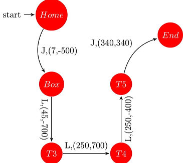
The smooth command will round corners of a path by a given length (mm) or percentage(%).
Pause instructions can be added for the robot to wait for an object or for a given time interval.
Test the program in a loop, fix any run-time errors or singularity errors if there are any.
Generate and study the robot manipulator scrip.
A video of the setup in work can be seen here.
Lab task:
Create an environment with an ABB IRB-1600-6/1.2 robot manipulator, with a spindle tool attached. The working environment will have a vacuum table( normal table object), with a 50 cm x 50 cm steel sheet (plane object), placed in [x = 458.086 mm, y = 506.236 mm, 0mm, 0°, 0° -120°] configuration.
The task is to etch the sides of the steel sheet, and to cut a disk with radius of 25cm out of the middle of the sheet.
Sub tasks:
-
Give the coordinates of the vertices of the steel plane, if the working frame is fixed to the corner of the table (Manually or using Matlab).
-
Calculate the coordinates of the circle motions required for the central circular cut (assuming 0mm cutting width).
-
Create the following robot routine:
-
Home the manipulator.
-
Move the tool to the starting vertex with Joint movement.
-
Etch the edges of the steel sheet with Linear motion.
-
Home the manipulator.
-
Pause the manipulator for 600 ms (tool change).
-
Move the tool to the starting point of the circular cut with Joint movement.
-
Cut out the central disk using circular motion defined by the above calculated coordinates.
-
Home the device.
-
Generate the program script.
-
If everything is done correctly you should see a task similar to this.

